Difference between revisions of "Main Page/PHYS 3220/Excitation Potentials"
| Line 16: | Line 16: | ||
<h1>Procedure</h1> | <h1>Procedure</h1> | ||
| + | |||
| + | <h2>Required Components</h2> | ||
| + | <ol> | ||
| + | <li>Franck-Hertz Unit</li> | ||
| + | <li>Sweep Generator </li> | ||
| + | <li>DC amplifier</li> | ||
| + | <li>Power Supply for DC amplifier</li> | ||
| + | <li>Oscilloscope</li> | ||
| + | <li>Current Amplifier</li> | ||
| + | <li>Filament AC voltage power supply</li> | ||
| + | <li>Variable Resistor</li> | ||
| + | <li>DC bias power supply</li> | ||
| + | <li>Variac</li> | ||
| + | </ol> | ||
| + | |||
<p>The experimental circuit is shown in Fig. 2. <b>This will be set up prior to the experiment but should be checked, make sure you understand the purpose of each component before proceeding.</b> Switch on the heater for the Franck-Hertz tube. Since the vapour pressure of Hg is low at room temperature (p ≈10-3 mm. of Hg) the temperature must be raised to 180ºC to reduce the mean free path of electrons in the Hg gas. The heating might take some time; make sure the temperature stabilized at the desired value before proceeding. Watch the thermometer to check the stability of the temperature. Connect the 12.6 Vac transformer and adjust the potentiometer A to make the plate (V<sub>1</sub>) = 1.5 volts NEGATIVE with respect to the grid.</p> | <p>The experimental circuit is shown in Fig. 2. <b>This will be set up prior to the experiment but should be checked, make sure you understand the purpose of each component before proceeding.</b> Switch on the heater for the Franck-Hertz tube. Since the vapour pressure of Hg is low at room temperature (p ≈10-3 mm. of Hg) the temperature must be raised to 180ºC to reduce the mean free path of electrons in the Hg gas. The heating might take some time; make sure the temperature stabilized at the desired value before proceeding. Watch the thermometer to check the stability of the temperature. Connect the 12.6 Vac transformer and adjust the potentiometer A to make the plate (V<sub>1</sub>) = 1.5 volts NEGATIVE with respect to the grid.</p> | ||
Revision as of 10:55, 6 September 2012
Contents
Excitation Potentials of Mercury: The Franck-Hertz Experiment
Introduction
One of the most direct proofs of the existence of discrete energy states within the atom was first demonstrated in experiments on critical potentials, performed initially by Franck and Hertz in the early 1900's. Studying the way electrons lose energy in collisions with mercury vapour, they laid the basis for the quantum theory of atoms by observing that the electrons give energy to internal motion of mercury atoms in discrete units only.
The collision of a neutral atom with a fast particle (e.g., an electron) may result in the excitation or ionization of the atom. A slow electron in an elastic collision can give very little of its kinetic energy to the translational motion of a mercury atom (without changing the energy state of the atom) - just as a ping-pong ball cannot effectively move a billiard ball. If a moderately slow electron has enough kinetic energy to overcome an atomic excitation threshold (several eV) the collision may be inelastic and much of the energy of the electron can go into exciting a higher state of the atom. The energy in electron volts (eV) necessary to raise an atom from its normal ("ground") state to a given excited state is called the excitation potential for that state. For sufficiently high scattering energy of the impinging electron even ionization may occur.
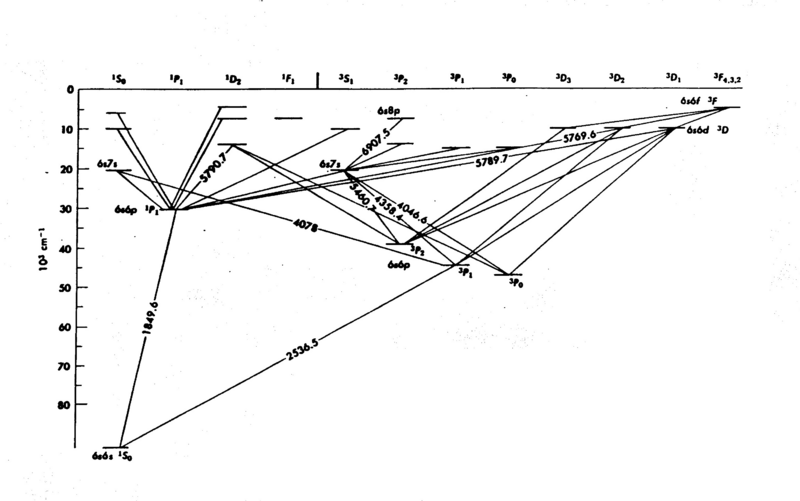
The energy levels of mercury (Hg) are shown in Fig. 1; it is easy to see that the internal structure is complicated - a consequence of the many electrons in the atom. The diagram gives considerable information you need to know for this experiment. The numbers associated with the lines drawn between the energy levels are wavelengths (in Angstroms Å). In the present experiment we explore only the energy levels 63P on the diagram, the first group of excited states. The electrons do not acquire enough energy to excite many of the other levels.
The Franck-Hertz apparatus consists of an evacuated glass envelope containing a cathode, screen, plate and a small drop of mercury, which can be vaporized by heating. The plate is always kept slightly negative with respect to the grid (that acts as an anode, i.e. accelerates the electrons) and both are set at various positive voltages with respect to the cathode. As the grid potential is raised, the plate current increases accordingly. For accelerating voltages below 5V all collisions with mercury atoms will be elastic (kinetic energy below about 5 eV). Hence, these electrons are energetic enough to overcome the negative plate-grid potential and are collected by the plate. The current flowing in the tube depends upon both the number of charged carriers (electrons) and their velocities (j = nev). Thus a significant change in the particle velocity can affect the size of the current. Once electrons with more than about 5eV energy excite a mercury atom, they slow down and the current flowing in the tube drops. If there is a larger voltage across the tube so that the electron can be re-accelerated to ~ 5 eV after giving it up once in the first collision, then we can see decreases in the current at higher voltages corresponding to a repeated inelastic collision. This process can yield a cyclic rise and fall of the current with the voltage.
|
Figure 1 - Energy Levels of Mercury.
|
Procedure
Required Components
- Franck-Hertz Unit
- Sweep Generator
- DC amplifier
- Power Supply for DC amplifier
- Oscilloscope
- Current Amplifier
- Filament AC voltage power supply
- Variable Resistor
- DC bias power supply
- Variac
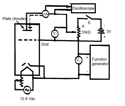
The experimental circuit is shown in Fig. 2. This will be set up prior to the experiment but should be checked, make sure you understand the purpose of each component before proceeding. Switch on the heater for the Franck-Hertz tube. Since the vapour pressure of Hg is low at room temperature (p ≈10-3 mm. of Hg) the temperature must be raised to 180ºC to reduce the mean free path of electrons in the Hg gas. The heating might take some time; make sure the temperature stabilized at the desired value before proceeding. Watch the thermometer to check the stability of the temperature. Connect the 12.6 Vac transformer and adjust the potentiometer A to make the plate (V1) = 1.5 volts NEGATIVE with respect to the grid.
Setting up the Ramp Generator
The HP3325A Synthesizer/Function Generator will be providing a sawtooth ramp for the accelerating voltage of the electrons. It requires to be set up in a particular way.
- Select the sawtooth waveform from the set of Function buttons. (Second function from the right).
- Press button labelled "“40pvp, 40mA, 0-1MHz” beside the "Signal" BNC output.
- Set the frequency to be 0.1Hz.
- Set the Amplitude to be 20 V.
- Set the offset to be 10V.
You should now see the effect of this sawtooth waveform on the analog voltmeter V2.
Setting up the Oscilloscope
The Tektronix TDS2014B will be used to record the waveform.
- The ouput from the rear of the Picoammeter should go to CH1 of the oscilloscope.
- Set the TimeBase to be 1 s/Div.
- From the Trigger menu, set the Mode to Auto.
Note that the oscilloscope is not triggered. It has a timebase of 1 s/Div, and 10 divisions across the screen, so the screen shows 10s of data- corresponding directly to the 0.1Hz of the function generator.
The sharp discontinuity in the trace (one the filament is on and the Picoammeter setup properly) corresponds to the moment when the sawtooth jumps from 30V to 0V, so can be used in your data reconstruction. Note that any change on the oscilloscope (timebase, Volts/Div, etc...) causes the trace to reset to the left of the screen. You may find is comfortable if you can get the 30V to 0V discontinuity to be at the extreme left or right of the screen by changing a scope setting at just the right moment.
When the temperature is stable you can record the current-voltage characteristic of the Franck-Hertz tube. The current-voltage trace can be recorded from the connected oscilloscope after closing the (S) connection. Make sure the signal you observe does not have horizontal clipping (the peaks cut off), this can be fixed by changing the settings of the Pico-Ammeter or the potentiometer next to the 12.6 Vac transformer. (What is the meaning of the vertical cut-off?)
Record an I-V curve for a lower oven temperature (between 150ºC and 165ºC). Repeat for other temperatures, so that you may comment on the effect of the Hg pressure in the tube.
|
Figure 2 - Experimental Setup.
|
Measurements
Find as many values as you can of the excitation energy ("excitation potential") from your record. Repeat these measurements for 10 different temperature values. Perform a full error analysis and compare your results with the expected values.
Questions
- What effect do you find the temperature has on the I-V trace? Show this graphically.
- Explain the effect of changing the grid-to-plate voltage (V1)?
- Find out what is meant by "contact potential" in the Franck-Hertz tube and explain how it could be determined. Can you estimate it from your record?
- Determine from simple classical mechanics (using a head-on collision with recoil at 180 degrees) what fraction of an electron's kinetic energy can be transferred to a mercury atom in an elastic collision. Derive an approximate value of the fraction.
- Why are the other levels not observed? (e.g. 63P2, 63Po, 61P1.)
References
- Brehm, J., Mullin W, Modern Physics, p. 168
- Halliday, D., Resnick, R., Physics I, pp. 522-24.
- Carpenter, K.H., Amer. J. Phys. 43 (1975) 190.
- Hanne, G.F., “What really happens in the Franck-Hertz experiment with mercury?” Am. J. Phys. 56 (1988) 696.
- Huebener, J.S., Amer. J. Phys. 44 (1976) 302.
- Liu, F.H., “Franck-Hertz expt. with higher excitation level” Am. J. Phys. 55 (1987) 366.
- Preston, D., Dietz, E., The Art of Experimental Physics, pp. 197ff.

