Main Page/PHYS 3220/Interferometer
The Michelson Interferometer
In this experiment a Michelson interferometer is calibrated using a known mercury line, and then used to make a wavelength determination for the Na doublet. In addition, the index of refraction of a piece of plastic, and that of air at room pressure is determined.
Introduction
The Michelson interferometer is well known for the role it played in finding that the speed of light is the same in every reference frame, and thus to begin the development of the special theory of relativity. It is a simple set-up by means of a half-silvered and two ordinary mirrors to split a beam of light into two, allowing one beam to travel a different path length than the other in order to superimpose them. Small variations in the path length difference d allow us to observe the wave nature of light, i.e., to observe how the two beams can add to produce an interference pattern. An observation of the interference pattern as d is changed allows us to draw conclusions about the wavelength of coherent monochromatic light.
An interferometer is one of several instruments to demonstrate the wave nature of light (ref. 1). Other important two-beam experiments are, e.g., the Fresnel mirror, Young’s double-slit experiment, a thin film, or a grating (cf. the spectrometer used in Expt 9). A more sophisticated version of the interferometer used extensively in research is the Fabry-Perot interferometer. Use the references to understand how these interferometers work and what is meant by spatial and temporal coherence of light coming from an extended source.
 Figure 1 - The Michelson Interferometer.
|
In Fig. 1 the schematic diagram is shown for the M.I. with the semi-transparent mirror positioned at 45 degrees splitting the source beam into two halves that then travel toward the mirrors M1 and M2. The electric field associated with a monochromatic planar wave with circular frequency ω=2πc/λ, and wavenumber k=2π/λ is given by
|
| (1) |
The waves that are reflected at M1 and M2 are again split by the half-silvered mirror. We are interested in the signal arriving at P (the observer’s eye). Let M2' be the virtual image of M2 as seen by P (along the line of sight of M1), and d be the separation between M1 and M2'.The mirrors are carefully adjusted such that M1 and M2' are parallel. The difference in path length of the light is thus given by 2d. The amplitudes of the two waves reaching the point P simultaneously are equal, and independent of the reflectivity of the half-silvered mirror (!), whereas their respective phases φi are going to be different depending on the traversed path lengths.
|
| (2) |
From (1) it is obvious that the phase difference depends on the path length difference 2d and on the wavelength of the monochromatic light:
|
| (3) |
The time-averaged intensity of the light IT observed at P is given by
|
| (4) |
Consequently the M.I. acts as a wavelength-dependent mirror, and depending on the phase difference Δφ , IT varies between 0 and the time-averaged incident intensity I0.
Equations (3,4) yield the conditions for constructive and destructive interference respectively: complete passage of the incident light occurs for the wavelengths determined by Δφ = m2π, i.e.,
|
| (5) |
while complete reflection occurs for Δφ = (m+1/2)2π, i.e.,
|
| (6) |
For wavelengths in between these values the light is partially reflected and partially transmitted. Note that according to eq. (4) the intensity is independent of the order m. This is not exactly realized in practice due to imperfections in the glass.
The mathematical description of the two waves for the M.I. still omits one point. Light reflected at a boundary surface from an optically rare to a dense dielectric medium experiences a phase change of π (ref. 4,5). Considering the M.I. for d=0, we find from eq. 5 that m=0 corresponds to the condition for maximum intensity. If we treat the half-silvered mirror as a thick glass plate, then if we follow the path of the two beams we observe that one beam suffers an additional phase change of π while reflecting at the back surface of the mirror. Thus, destructive, and not constructive, interference should occur. However, the treatment is non-trivial as the metallic coating (of a few atomic layers) can introduce phase changes in both the transmitted and reflected waves. This can introduce an overall phase difference Δφ between 0 and π depending on the nature of the reflecting surface. The effect of this phenomenon when using white light will be considered in a later section.
Usually the light entering the interferometer is not parallel, but somewhat divergent. The partial beams have an angle of inclination θ as shown in Fig. 2. Owing to the several reflections in the real interferometer we may now think of the extended source as being at L, behind the observer, and as forming two virtual images L1 and L2 in M1 and M2'. The path length difference 2d now depends on θ, and is due to axial symmetry with respect to the central axis owing to this. A system of circular fringes is produced in the field of view. The difference in path length for beams with inclination θ becomes 2d cos(θ), and thus the condition of constructive interference becomes 2d cos(θ) = mλ. The phase difference for the partial waves arriving at P is given by
|
| (7) |
 Figure 2 - Formation of circular fringes for a divergent beam.
|
If the mirror M1 and the virtual image M2' are not exactly parallel, fringes will still be seen with monochromatic light for small path differences, but the pattern loses its circular shape (ref. 2,6). The fringes appear as parallel lines that can be adjusted, e.g., to be vertical in the field of view.
Thus, one of the mirrors in the M.I. - usually the stationary one - has tilt controls so that one can tune the instrument to produce either a circular, or a parallel pattern of fringes of equal intensity.
You will note that Fig. 1 has an additional parallel plate of glass, B. The light reflected from M1 passes through A three times before reaching the eye. The light reflected from M2 passes through A once and through B twice. Thus, the purpose of the compensating plate B is to make the two optical paths, ray (1) and ray (2), traverse equal amounts of glass. This is not essential for producing fringes in monochromatic light, but it is indispensable when white light is used.
Experimental Procedure
NOTE:The interferometer is a precise optical system that can be easily damaged. DO NOT put your fingers on any reflecting surface.
- Initial adjustment of the Michelson Interferometer
Verify that the components are in the correct position for the Michelson interferometer. The angular tilt of mirror M1 is fixed, but it can be displaced using a linkage (lever) to a micrometer. Mirror M2 can be tilted but not displaced. Place the mercury lamp before the diffusing screen and affix a pointer needle vertically to the screen.
CAUTION: The mercury lamp emits UV radiation. You have to wear safety glasses to protect your eyes. Never operate the mercury lamp without a glass plate attached.
Turn the mercury lamp on and align the eye with the viewing axis about ten inches (25 cm) from the instrument. Two pairs of reflected images of the pointer will be seen, one coming from reflection at the front surface of A, and the other from reflection at its back surface. When the tilting screws on M2 are now turned until one pair of images falls exactly on the other, the interference fringes should appear. Acquaint yourself with the instrument, and try to obtain a circular, as well as a parallel pattern. Try to produce a circular pattern with a small number of fringes?
As mirror M1 is moved a distance d, the pattern of bright (dark) fringes shifts according to eq 5 (eq. 6). Thus, if one changes d and counts how many bright (dark) fringes pass a reference point (e.g. the image of the pointer), the wavelength λ of the monochromatic light can be determined. On the other hand, one can use this method with light of a known wavelength in order to calibrate the mechanism for the mirror movement, i.e., to determine the distance d that corresponds to a given reading on the micrometer. In the following steps you will first perform a calibration of the linkage, and then determine λ for a source of unknown wavelength.
Calibration of the mirror movement
The mercury lamp produces a spectrum of lines of discrete wavelengths (consult a spectral chart to verify, cf.. Table I in Exp. 9) .The green filter used in front of the Hg lamp isolates the 5461Ǻ (=546.1 nm) line. Measure the distance on the micrometer screw that produces a shift of 50 fringes. Repeat the measurement for ten sets of 50 fringes. Carefully deduce the mechanical ratio of the micrometer-mirror linkage with its error.
- Determination of the wavelength of the Na doublet lines
It is possible to use the Michelson interferometer to measure the wavelength difference between two lines closely spaced in wavelength and of similar intensities, without finding the wavelength of either line to high precision. In this part we determine the separation and average wavelength of the sodium doublet, known for its characteristic yellow lines.
The two lines with wavelengths λ1 and λ2 are closely spaced for the following reason. At the level of nonrelativistic quantum mechanics a single line is predicted for the transition corresponding to a de-excitation of the Na(3p) to the Na(3s) ground-state level. Note that in contrast to the hydrogen spectrum (a pure -Ze2/r potential) the Na energy spectrum does have a dependence on the principal quantum number n as well as on the magnitude of angular momentum l , i.e., 3s and 3p are not degenerate. In a more refined treatment the orbital angular momentum (l = 1) state Na(3p) can couple with the electron spin (s = 1/2) in two ways: a state with total angular momentum projection jz = 3/2, and another state with projection jz = 1/2 along the z-axis. The energies for these states are slightly different. The separation of the two wavelengths (that you determine in this experiment) is a measure of the effect of the spin-orbit coupling: a tiny energy offset that arises as a result of the interaction between the magnetic moments associated with the orbital and spin angular momenta of the electron (cf.. ref. 3).
The presence of a superposition of two monochromatic waves in the M.I. complicates the analysis somewhat. One obtains a superposition of two slightly different fringe patterns due to the difference between the wavelengths λ1 and λ2. For some choices of d the fringes for the two wavelengths are aligned, while for other values the maximum of intensity for one wavelength lies between the maxima of the other wavelength, leading to uniform illumination (as opposed to a fringe pattern). The difference in the mirror displacements for which a uniform field is observed can be used to measure the wavelength difference as shown below.
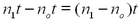
When a certain point in the visual field is a maximum for both wavelengths (aligned fringes) then the phase differences introduced by the path difference between the mirrors must be integer multiples of 2π. Let δ1 be the phase difference for wavelength λ1 between the beams arriving at P from the two mirrors (i.e., δ1= φ2 - φi for λ1). Then it follows that δ1 = (2π/λ)2 d = m1(2π), where m1 is an integer, and correspondingly for the other wavelength δ2 = m2(2π), where m2 is another integer.
The difference between the phase differences is
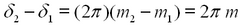
(8) where m is an integer. We denote the mirror separation for which this condition is satisfied by d=dm. If we move the mirrors smoothly until the next condition of maximum fringe resolution is obtained, we have two new phase differences δ1′ and δ2′ for which

(9) The mirror separation at this point is denoted as dm+1.
Equation (8) yields
while from equation (9)
From the two equations and the geometric mean
one obtains for Δλ=λ2 - λ1
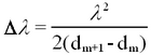
(10) This procedure is also applicable between conditions of minimum fringe contrast; it is up to the experimenter to decide which yields more accurate results.
By using the results and the technique of the calibration experiment the mean wavelength λ can be found (you should make 5 measurements of λ); also Δd = dm+1 - dm can be measured for a number of successive positions at which the pattern is least distinct (measure Δd for 10 successive positions and average the results). From this, Δλ, λ1 and λ2 can be evaluated.
Note that you should use the M.I. in the same region of the micrometer screw as used while calibrating the instrument. Also, be careful about "backlash" in micrometer readings.
Observation of inhomogeneities of the refractive index
The fringe pattern is sensitive to changes of the refractive index of the medium in the light path. You can put a piece of glass into one arm of the interferometer and observe the variation of fringes from monochromatic light due to inhomgeneities in the glass. The variation in the fringe pattern from the change in the medium is commonly used in interferometry, e.g., to determine the refractive index of a medium, or (if the latter is known) to study the physical properties of a gas (e.g., density). You can see this effect by using a blow dryer to induce changes in one arm of the M.I.
White light fringes - Measurement of the refractive index
If a source of white light is used, no fringes will be seen except for a path difference so small that it does not exceed a few wavelengths. In observing these fringes, the mirrors are tilted slightly as for localized fringes, and the position of M1 is found where it intersects M2' (cf. ref. 2, pp248-50). From eq. 5 the condition d = 0 implies m = 0 for all wavelengths resulting in a central fringe that is either dark (no colour) or bright (all colours superimposed). In our experimental set-up the central fringe is bright bordered by dark bands (for the reasons discussed in the theory section).
The d = 0 position is usually hard to find using white light only. It is best to use a Hg source to locate the position where the localized fringes become straight in the field of view. The lamp fixture has two light sources: a mercury discharge tube and a white light tungsten lamp, that are controlled by separate switches. Use the Hg source to locate straight parallel fringes and then turn on the white light. The mercury fringes will now appear against a white background. Turn the path length control slowly until a distinctive central white band flanked by dark fringes appears in the middle of the field. Now switch off the mercury lamp. The fringes will remain visible.
Discuss the spectral variation that you observe in the field of view, i.e., why the first few higher-order fringes are coloured followed by a broad white illumination. What is the wavelength range for visible light?
Using white light fringes you will measure the refractive index of a piece of plastic. When you insert the plastic into the path between the fixed mirror and the dividing mirror you will see that the fringes disappear. Note where (on the micrometer) they appeared before inserting the plastic and then carefully and slowly search a few turns on either side of this position until you find white-light fringes. Do not try to re-adjust the mirror tilt controls.
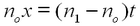
You can measure the distance the mirror moved to re-establish the fringe system. (Several readings will give an average value x). If n1 is the index of the plastic and no ~ 1 is the index for air (n0 = 1 for vacuum), then the optical path length in the plastic (thickness t) is n1 t, while the path length in the same distance t in air is no t. The additional path length introduced in the arm of the interferometer is thus
(11) This path length is equal to the amount by which the mirror must be reset (after inserting the plastic) to regain the white-light fringes:
(12) From this condition, find n1 after measuring t using a micrometer.
The index of refraction of air at atmospheric pressure
It is possible to see the change in the optical path that occurs as air is removed from a cell positioned in one arm of the Michelson interferometer. This is used for a quantitative measurement of the index of refraction of air.
Suppose that m fringes pass the reference point in the visual field as one changes the pressure in the cell by ΔP. A passage of one fringe corresponds to a change in the optical path length by λ. Let the index of refraction of air at pressure P be μ(P). At zero pressure, i.e., for a vacuum, μ(0)=1. Thus, the change in the optical path due to the presence of air at pressure P in a cell of length t in one arm, as compared to vacuum, corresponds to a total passage of N fringes:
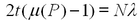
(13) Place the cell in one arm of the interferometer and attach the hand pump. Align the interferometer to see monochromatic fringes from the mercury lamp with a green filter. Then verify that the fringes move when air is exhausted from the cell. Use the pump gently. This pump cannot provide a very good vacuum. You will need to extrapolate your results to a perfect vacuum condition. Note that the gauge starts at zero corresponding to atmospheric pressure, and as you evacuate the cell the pressure reading increases. (You may have to tap the pressure gauge gently to ensure that the needle is not sticking). Begin evacuating the cell, and record the pressure changes associated with the passage of m = 10 fringes. Are the changes in pressure (for a fixed number of fringes) approximately equal? Calculate the index of refraction at room pressure. Discuss the sources of error in your measurement.

References
- Halliday, Resnick, Walker, Fundamentals of Physics, chapter 40.
- Jenkins, White, Fundamentals of Optics, McGraw-Hill 1957
- Serway, Moses, Moyer, Modern Physics, Saunders 1989, page 229
- Hecht, E. , Optics, Addison-Wesley 1987.
- Tenquist D.W., Whittle R.M., Yarwood J., University Optics, Iliffe Books, London 1969.
- Lipson S.G., Lipson H., Tannhauser D.S., Optical Physics, 3rd ed., Cambridge Univ. Press,1995.