Main Page/BPHS 4090/microscopy I
Contents
Required Components
- Diatom slide
- Stage micrometer slide
- Stained and unstained baboon eye slides
- Fresh onion
- Knife and tweezers
- Toothpick or popsicle sticks
- Blank slides and coverslips
- Syringe of vaseline with pipet tip end
- Distilled water
- Immersion oil
- Nikon upright microscope and CCD camera
- USB stick for transferring data and images for processing and report generation
Objectives
Students will get a refresher on the optical light path of microscopes as well as working with digital acquisition software and data processing. Building off of previous knowledge, the students will explore light contrast modes for unstained samples like darkfield imaging and phase contrast imaging. In the first part of this lab these modes will be compared with standard brightfield illumination on stained and unstained specimens. In the second part darkfield imaging will be used to measure the cytoplasmic streaming rate of spherosomes in living onion cells.
Introduction
Imaging has become a vital tool for researchers in virtually all aspects of modern biophysics. Recent advances in microscope technology as well as labelling techniques and gene and protein manipulation methods have led to breakthroughs in our understanding of biological processes. In order to take advantage of these methods you, the biophysicist, need to understand some of the fundamental techniques and concepts in microscopy. You already have experience with microscopes, and this lab will build on that knowledge and get you familiar with more advanced methods as well as working with acquisition software.
The brightfield (transmitted light) imaging mode is something you have already been exposed to. Brightfield imaging mimics the human optical system and is measured in terms of colour and light intensity absorbed by a sample. The contrast method is based off of colour specific absorption of light by the dyes added into the specimen. When working with certain samples, particularly live specimens, the addition of exogenous contrast agents isn’t always feasible as they can potentially interfere with the organism or cells under observation. In this lab we will focus on some specialized microscope techniques to look at unstained samples in a way that lets you observe their morphology without the addition of foreign compounds. The imaging modes you will be using are:
- Brightfield: where samples contain little natural contrast and dyes are added to impart artificial colour
- Darkfield: where photons observed are mostly those that have been scattered by structures within the samples
- Phase Contrast: where optics will be used to visualize changes in the optical path length of samples
A refresher on optical microscopy and imaging theory is included in Appendix 1. Please refer to this section to review some of the fundamental concepts in microscopy. If you feel comfortable with this content you do not have to read through it thoroughly. It has been included as optional background material.
Brightfield Staining
Most biomedical microscopy specimens contain very little intrinsic contrast when viewed directly with transmitted light. For example, to make specimens such as the tissue sections you are using in this lab easier to visualize, stains and dyes are used. These compounds impart additional contrast and enable discrimination of morphological features based on their differential colour absorption across the visible spectrum.
By far, the most common type of stain used in biological microscopy is Haematoxylin & Eosin (H&E). Haematoxylin stains basophilic chemical structures such as DNA in the nucleus dark purple, while Eosin will stain the cytoplasm and extra-cellular regions a shade of pink. When oxidized, haematoxylin forms a structure called haematein. Haematein is a compound that forms strongly coloured complexes with metal ions, most notably Fe(III) and Al(III), and it is these coloured complexes which give the blue/purple colouring seen in the nuclei of H&E sections. H&E staining allows pathologists to observe the density and shape of nuclei in tissue sections, and is the gold standard in the diagnosis of many types of Cancer.
Shown in Figure 1 is a sample of an H&E stained tissue section from a rabbit brain. A low resolution image shows a brain tumour as the dark purple mass, and the zoom view shows the border between tumour and healthy tissue. Note the dark purple staining of the cancerous nuclei, and how densely packed they are.
 Figure 1 - H&E stained section of mouse brain. Shown inset is a zoomed view showing the cluster of nuclei in a
brain tumour (dark purple patch in larger image).
|
Darkfield Microscopy
Dark-field microscopy permits the detection of unstained small biological objects which otherwise provide insufficient contrast under transmitted light observation. In a dark-field microscope a special condenser or aperture stop is used to produce light rays that normally miss being collected by the microscope objective’s collection NA. When this light interacts with a scattering object such as a biological sample, light is scattered into the collection NA of the objective and detected (Figure 2). While it is often the least used of the contrast modes you are exploring, it is relatively simple to adapt a standard microscope for darkfield imaging, and the images produced can be quite striking.
The aperture stop in a darkfield condenser causes light to focus on the specimen in a ‘hollow’ cone. The aperture stop is sized in such a way that this hollow cone is larger than the collection NA of the objective being used, so most of the light put out by the lamp is not detected. Any light that interacts with the sample will be scattered or refracted into the collection NA of the objective being used (light grey region) and detected. Light that does not pass through the sample does not enter the objective’s collection volume, and is thus not detected (gold region).
 Figure 2 - Darkfield illumination path in a typical microscope. An aperture is used to create a ‘hollow’ beam of light
and is focused at the sample. Light that does not interact with the sample (scattering, refraction, reflection, etc) is
outside of the lens NA and is therefore not detected. Light that is scattered or refracted by the sample enters the
collection NA of the objective and is detected.
|
Since there is very little scattering from the glass slides which the samples are mounted on, the image you see appears as a bright image on a dark background, hence the name 'darkfield' microscopy. This microscope method is very useful for viewing small bacteria as well as blood samples. You will also notice that if you are using slides that have not been thoroughly cleaned the dust and dirt on the slide surface will produce a very strong darkfield signal. It is always good practice to clean microscope slides before observation, but this is even more important for darkfield imaging.
An ideal sample to demonstrate darkfield imaging is an onion cell, as it is readily available, cheap, and exhibits quite dynamic activity under darkfield illumination. The endoplasmic reticulum of onion cells forms a network of interconnected tubules within, within which highly refractile objects like mitochondria and sphereosomes are propelled by actin filaments within the cells cytoplasm. An excellent figure depicting the structure and location of this network in an onion cell is found in figure 1 of the paper "Onion Epidermal Cells in Relation to Microtubules, Microfilaments, and Intracellular Particle Movement” by Stromgren-Allen and Brown, which should be provided to you as a separate pdf file (a copy is also stored in the ‘Onion Sample’ folder on the PC desktop). It is recommended that you read this paper as well as “Isolation of Spherosomes (Oleosomes) from Onion, Cabbage,and Cottonseed Tissues” by Yatsu et al, which includes an electron microscope and compositional analysis on the particles streaming around in this tubule network.
Phase Contrast Microscopy
Before getting into details regarding phase contrast imaging we should first review a concept which you should have come across in your studies, the optical path length of an object. It is a relatively simple concept, which essentially states that the optical path length of light traversing an object is equal to the physical length travelled (L) multiplied by the index of refraction (n) of the medium the light is travelling in. Thus, an object can be the same thickness throughout its volume, but changes in the index of refraction make its optical path length vary. Our eyes are sensitive to amplitude (intensity), but not sensitive to changes in light phase induced by optical path length differences. These are the changes we are visualizing in phase contrast imaging.
Optical Path Length = n X L
Phase contrast microscopy produces image intensities that vary as a function of specimen optical path length, with very dense regions (those having large path lengths) appearing darker than the background. Alternatively, specimen features that have relatively low thickness values, or a refractive index less than the surrounding medium, are rendered much lighter when superimposed on the standard (positive) phase contrast (grey) background. Remember; as light travels through a medium other than vacuum, interaction with this medium causes its amplitude and phase to change in a way which depends on properties of the medium (Figure 3). Changes in amplitude give rise to absorption of light, which gives rise to colours. The human eye measures only the energy of light arriving on the retina, so changes in phase are not easily observed, yet often these changes in phase carry a large amount of information.
 Figure 3 - Two parallel light waves beginning perfectly in phase. The top wave travels through a homogenous
optical path while the bottom wave passes through a region where the index of refraction increases (boxed area).
The longer optical path of the bottom wave causes the waves to drift out of phase.
|
In a typical phase contrast microscope the phase variations introduced by the sample are preserved by the instrument, but this information is usually lost in the process which measures the light. In order to make phase variations observable it is necessary to combine the light passing through the sample with a reference wave and take advantage of constructive/destructive interference to highlight changes in phase. The resulting interference between the reference wave and the wave interacting with the sample reveals the optical path structure of the sample as intensity changes in the image observed or captured by a detector. The difference between a phase contrast and brightfield optical path are the addition of two matched phase rings etched accurately onto glass plates within the condenser as well as the objective lens (Figure 4). You can see that the rings are inverse patterns, and they must be aligned co-axially to maximize the phase contrast effect (see Appendix 2 for this procedure).
 Figure 4 - Location of the condenser annulus and phase plate in a PC light path.
|
Methods
A schematic of the microscope you will be using in this lab is shown in Figure 5. You can use this figure as a reference when performing the alignment and configuration of the microscope during the lab. Of particular note is to make sure you have the correct condenser fitted on the scope for this lab, which is the phase contrast condenser (NOT the DIC condenser). For aligning Kohler illumination use the centering screws on the base of the condenser mount (attached to the condenser focus block. For aligning the phase rings use the centering screws attached to the underside of the phase contrast condenser.
 Figure 5 - Schematic of the Nikon microscope you will be using in this lab. Refer to this figure to familiarize
yourself with the components and their locations.
|
Before performing any measurements or turning anything on, take a moment to study the labelled schematic of the upright microscope you are using. Below are some tips on how to start up the image acquisition software as well as for working with oil immersion objectives.
- Initial microscope setup – Kohler illumination
- Familiarize yourself with the microscope and the diagram included in this lab. We will not be using the fluorescence filter cubes or mercury light source for this lab (these will be used in the fluorescence lab).
- Turn on the power to the microscope transmitted light source (power switch is on the base of the microscope).
- Select the 10x objective and select the H&E mouse brain slide and place it on the specimen holder. Focus on the specimen.
- Close the field diaphragm down until you can see its effect in the oculars.
- Focus the condenser until you get a sharp image of the field diaphragm. You may need to gently push the focus block while turning the height adjustment knob as it is a tight at certain points in its travel.
- When the field diaphragm is in focus, you will see a red-blue flare surrounding it and as you open/close the diaphragm you will clearly see a circle getting larger/smaller.
- Now that the condenser height is positioned properly use the adjustment screws on the condenser to center the image of the diaphragm in the field of view.
- Open the field diaphragm so that it is slightly larger than the field of view you are looking at.
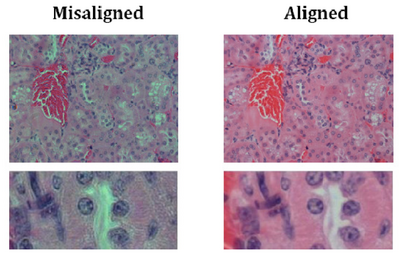
- You should now be set up for Kohler illumination which illuminates the sample with a
uniform field of light. An example showing poor contrast and colour reproduction
caused by non Kohler illumination is shown below for reference:
- If you change to a different objective you may need to re-adjust the diaphragm size or condenser height for optimal performance, but in general you should be ok for the rest of the lab.
- When aligning the phase contrast mode the Kohler illumination could shift slightly along X & Y, which should not matter much as long as the condenser height is ok and the aperture is opened slightly larger than the field of view.
- Working with immersion objectives
- One of the most critical points of working with immersion objectives is to be very careful with how much oil you use and to clean the objective thoroughly when finished.
- Also be careful not to get any oil on the non-immersion objectives. If this does happen, remove the objective from the microscope and clean it with the lens cleaning solution. Remove one of the microscopes eyepieces and use it to examine the lens and ensure it is clean. Use the lens to look at a specimen to confirm it is clean. If it is still dirty, repeat the cleaning procedure.
- Move the stage down and use the light from the condenser as a reference for where to place the drop on the specimen. You don’t need much immersion oil here, if you use too much it will be a waste and make it more difficult to clean the slide when we are finished.
- Carefully finish rotating the 100x or 40x objective in place and re-focus on the sample. At this point you can freely move around the slide, just try and keep the X-Y motion of the sample to a slow and steady pace or else you will lose oil quickly and have to add more. If you make slow, controlled motions the oil will not spread out as much.
- After acquiring your images, lower the stage and remove the slide. Carefully clean the slide and lens using a kimwipe and the supplied cleaning fluid.
- When you are finished with the lab thoroughly clean any immersion objectives used as well as slides that are part of the permanent lab (ie, micrometer, diatom slide, stained slides). This is a critical step, as over time oil that is not cleaned can degrade image quality and even render the very expensive objectives on the microscope useless. The objectives will unscrew from the turret, and using one of the eyepieces you can examine the lens after cleaning it to ensure there is no residual oil (ask your lab instructor to show you how to do this if you are unsure).
- Getting ready for acquisition and digital image capture.
