Difference between revisions of "Main Page/BPHS 4090/microscopy II"
| Line 49: | Line 49: | ||
colour filter set to separate the excitation and emission photons.</p> | colour filter set to separate the excitation and emission photons.</p> | ||
| − | <table width= | + | <table width=400 align=center><td> |
| − | <p align=justify>[[File:Fl_fig1_states.png | + | <p align=justify>[[File:Fl_fig1_states.png|380px|border|center]] |
<b>Figure 1</b> –Schematic representation of the process of fluorescence. Light absorbed by a molecule causes it to move | <b>Figure 1</b> –Schematic representation of the process of fluorescence. Light absorbed by a molecule causes it to move | ||
into an electronic excited state. After losing some energy to heat/vibration/rotation, a fluorescent photon is | into an electronic excited state. After losing some energy to heat/vibration/rotation, a fluorescent photon is | ||
Revision as of 11:42, 10 September 2010
Required Components
- Stage micrometer slide
- Chroma fluorescent slide kit
- Fluorescent bead slide
- Fluorescent microchannel slide
- Fresh onion
- Knife and tweezers
- Toothpick or popsicle sticks
- Blank slides and coverslips
- Syringe of vaseline with pipette tip end
- Distilled water
- Immersion oil
- Nikon upright microscope and CCD camera
- Usb stick for transferring data and images for processing and report generation
Objectives
In this lab students will expand their use of optical microscopes to include fluorescence imaging, which allows for highly specific labelling of proteins and complexes within the specimen. Fluorescence is often complimented with Differential Interference Contrast imaging (DIC), and this will also be explored during these experiments. Fluorescence really is a quantum mechanical phenomenon, and the emphasis here will be on understanding what is physically happening within samples that are fluorescently labelled. Understanding the principle of fluorescence filtering and getting a feel for the light intensity levels being generated is critical for fluorescence microscopy.
Introduction
Fluorescence microscopy is a very powerful tool allowing for the observation and quantification of biological samples. You have seen previous labs how unstained samples contain very little contrast, and through the addition of light absorbing dyes and stains or special optics, the morphology and structure of samples can be readily observed. Fluorescence microscopy uses the same concept of imparting artificial contrast to samples, but has several advantages over absorption based contrast methods. In this contrast method, fluorescent molecules are attached to specific structures within the specimen. Illuminating the specimen with a specific wavelength of light causes these fluorescent molecules to convert some of this illumination into a longer wavelength of light, which is then detected by a CCD or observed directly with the eye.
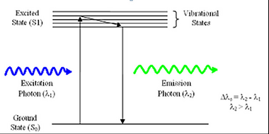
Fluorescence is a phenomenon first discovered by British scientist Sir George Stokes in 1852. The process involves the absorption of an incident photon of light by a molecule, referred to as a fluorophore, and subsequent emission of a second fluorescent photon a short time later (Figure 1). The energy transferred to the fluorophore after absorption causes the molecule to enter an excited energy state that is short-lived, typically on the order of 10-9 seconds (1/e value). During this time, some of the incident energy is lost due to vibrational/rotational motion and heat, among other things. When the molecule returns to the ground state, a fluorescence photon is emitted at a longer wavelength (lower energy). This fluorescence can be detected with a colour filter that passes the fluorescence emission and blocks the shorter wavelength excitation light. The difference in wavelength between the incident and outgoing photons is referred to as the Stoke’s Shift, and its phenomenon is the basis for all fluorescence imaging as it allows us to use a colour filter set to separate the excitation and emission photons.
|
Figure 1 –Schematic representation of the process of fluorescence. Light absorbed by a molecule causes it to move
into an electronic excited state. After losing some energy to heat/vibration/rotation, a fluorescent photon is
emitted and the system returns to the ground state.
|
