Main Page/BPHS 4090/Optical Tweezers of Onions
Introduction
The Physics of Optical Tweezers
The principle of optic tweezers was first proposed and discovered by Arthur Ashkin in 1970.[1] The principle relies on the refraction of light as it passes between media of differing indicies of refractions (symbolized by n), and the Gaussian profile of a trapping laser beam which is most intense at the central axis. Recall that a photon with wavelength λ and moving along the z-axis has of momentum equal to:
|
|
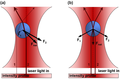
Note this this value is very small, and for large objects, the force from reflecting a photon is very small. However, for a large flux of photons (such as a from a laser) spread over a small area (focuss by powerful microscope objective) one can exert a meaning force on a small particle (such as micron-sized beads, or intercellular particles) As a photon passes through a transparent sphere of greater index of refraction than the surrounding medium, it will refract (change direction). This results in a change in momentum. As a reaction to this change in momentum, momentum is imparted to the bead in the opposite direction. The ray diagram for this effect is given in Figure 1. It is important to realize that the magnitude of the refraction of the photon depends on the difference of the indicies of refraction of the transparent sphere and surrounding medium.
|
Figure 1 - In part a), there is more laser intensity on the right of the bead due to the gaussian profile of the laser beam, and hence there is a net force to the right. In part b), the bead is centered and the net force in the left/right direction zero.
|
If the particle to be trapped is not so spherical, or scatters photons from the laser beam rather than refracts the photons, there will be a strong force pushing the sphere along the axis of laser propogation- like a water hose pushing a beach ball. It is imperative that the object to be trapped allows most of the light to pass through it, rather than bounce off its surface. You may have seen an example of optical trapping of latex beads in PHYS4061.
Structure of an Onion Cell
Plant cells have the general properties of a rigid cell wall, a large open vacuole, a nucleus, and cytoplasm containing organelles in the spaces between the cell walls and vacuole. The onion cell is a classic and often-used example of this structure. The organelles in the cytoplasm are small (between 0.5 and 1 micron), and roughly spherical in nature- prime candidates for optical tweezing with a laser. Organelles move throughout the cyctoplasm either along action filaments, and along the the endoplasmic reticulum network.
|
[2]
Figure 2: The onion cell
|
The organelles move throughout the onion cell only in the cytoplasm and not through the vacuole. There are strands of cytoplasm located sporadically thoughout the cell. These strands themselves can be seen by the imagining optics when focused appropriately. Within these strands of cytoplasm are actin fibers along which organelles are transported. The process by which this occurs is demonstrated nicely in the following animation. [1]
Preparation of onion epidermis for optical trapping experiments [3]
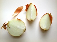
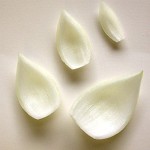
The common onion (Allium cepa) is often used to examine individual plant cells because of the ease of isolating sheets of cells that are one cell thick. The onion bulb can be sectioned into quarters or eighths. Then, the individual scale leaves can be separated.
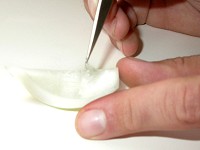
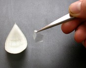
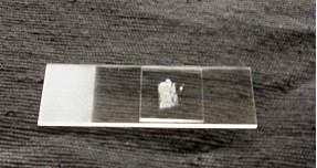
The exposed concave surface can be scored with a sharp razor blade. With a very fine pair of forceps, pieces of the epidermis can be lifted (note the transparency of the peel). Before doing so, have a microscope slide ready with a drop of distilled water (or artificial pond water) so that the peel doesn’t become dehydrated. Unlike the photographs, a thin strip of Vaseline will be placed on the microscope slide in a rectangular shape slightly smaller in dimensions then the cover slip. Having placed the epidermal peel in the water inside the Vaseline ‘dike’, carefully (gently) place the coverslip on top, pressing to create a seal around the perimeter.
 File:Onion5.jpg
File:Onion6.jpg
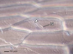
Now ready to place in the holder on the optical bench (left), here is what the cells will look like (right, the nucleus and transvacuolar strands are indicated).
Lab Exercise: Optical tweezing of onion cells
Apparatus
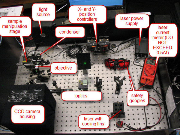
Although the apparatus used in this experiment may look unfamiliar and unlike anything you have used, closer inspection reveals that the system is just an open microscope mounted on its side. All basic components of microscope are laid out on the optics table- the objective, the sample manipulator, the light source and condenser, interacting light source, and the CCD camera. Since you are very familiar with details of a microscopy, this apparatus shoudln't prove intimidating. Instead of you interacting light source being used for fluorescence, you will use a powerful, monochromatic light source to interact with the sample.
Of course, this powerful light source is a laser. Solid-state lasers have made high-power monochromatic light cheap and available. In the recent past, one would have required a 1.5-meter long laser tube, with a power supply the size of an small filing cabinet to have the equivalent performance as the thumb-sized laser we will use. Figure 3 shows a general overview of the apparatus, with the major components indicated.
|
Figure 3 - Overview of the Apparatus
|
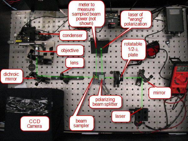
The laser/optical system is set up to ensure that the focus of the laser light through the objective is co-planar with the focus of the imaging optics of the CCD. The laser power is controlled by the combination of a1/2-λ plate and polarizing cube (see Figure 4). Light generated by the laser is mostly polarized along one axis. The 1/2-λ plate rotates this axis of polarization. The polarization cube separates light out into vertical and horizontal polarized light. Hence, at one position of the half-wave plate, the light will be predominately at the polarization required to pass straight through the cube. At 90 degrees to that rotation of the 1/2-λ plate, the light will be predominantly of the polarization to be directed out the side of the cube. Therefore, rotating the 1/2-λ plate will serve as our method of varying the laser power. In order to measure the laser power, a beam sampler is placed after the polarizing cube, and directs a fixed percentage of the laser beam to the side for measuring on a photodiode detector.
Once the laser power is controlled and sampled, it passes through a lens which adjusts the divergence of the laser beam such that the co-planar focus condition mentioned above is set. Following this, the laser is relfected into the 100 DIN oil objective off of a dichroic mirror. The dichroic mirror has the property of being a very strong relfector of 532nm, but a very weak reflector at shorter wavelengths. Therefore, light from the lamp used for imaging can pass the opposite way through the dichroic mirror and produce an image on the CCD camera.
|
Figure 4 - The optical system.
|
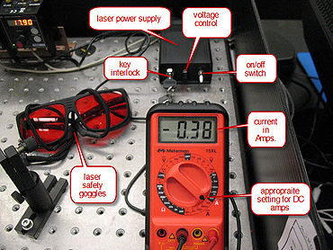
The laser is a DPSS (Diode-Pump-Solid-State) laser at 532nm rated to provide 100mW at 3V. Due to its power, it is classified as a Class IIIB laser. The procedure for operating the laser Figure 5) is as follows:
|
Figure 5 - Laser control system.
|
- Put on the safely goggles.
- Turn on the mulitmeter to measure DC current, on the 10A scale.
- Turn the key 90 degrees clockwise on the laer power supply.
- Enure the middle knob of the power supply is fully counterclockwise.
- Please the toggle switch in the "down" position.
- Slowly turn the middle knob clockwise while monitoring the current on the meter. You should be able to visibly see the laser on when the current increase above 0.18A. UNDER NO CIRCUMSTANCES ALLOW THE CURRENT TO INCREASE PAST 0.45A.
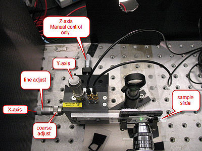
The microscope slide is mounted on a 3-axis precision translation stage (See Figure 6). The two axes transverse to the laser have piezo-controlled actuators which are controlled from the computer. All three axes can also be controlled by the coarse- and fine-adjust knobs located on the translation stage.
|
Figure 6 - The Translation Stage.
|
Computer Control
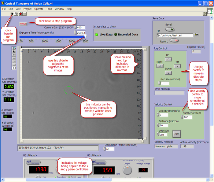
A LabView program is used to view the output from the CCD camera, and also to control the X-Y position of the sample. The layout of the user interface is described below.
|
|
Calibrate Optical Trap Depth
The goal of this experiment will be to determine the stength of the myosin motors which move the spherosomes along actin filaments. In order to achieve this goal you must first calibrate how strongly the spherosomes are trapped in the optical tweezers as a function of laser power. For this, we will use spherosomes moving in cytoplasmic medium near the cell walls, but not along actin fibers. The spherosomes are moving through the cytoplasm, adjacent to the endoreticulum network. Cell cytoplasm is a very complicated component of the cell, and can be characterized as a non-Newtonian fluid. The viscosity of the cytoplasm depends on the shear applied to the cytoplasm. For our purposes, we will take an educated guess of a viscosity of 20 times that of the viscosity of water. To determine the trapping force on the spherosome, we will move the spherosome through the cytoplasm as a constant velocity and see which velocity is great enough to dislodge the spherosome from the trap. The force exerted by the viscous cyctoplasm on a sphere is:
|
[4]
|
Where R is the radius of the sphere, is the viscosity of the cytoplasm, and v is the velocity of the sphere through the solution.
In order to have nice repeatable motion with the piezo translators, it is necessary to start at 0V applied to the piezo controlling the direction in which you want to move.
Method
- Determine the position of the laser. Notice that you can as you move the onion slide towards the microscope objecive using the z-xis manual control, the cover slip will come into focus first, and the laser position will be visible due to scattered light off the coverslip. Using the "region of interest" marker tool, place a ~2 micron circle around this position.
- Focus on the top cell wall. As you continue moving the onion slide closer to the microscope objective, first the top cell wall will come into focus, then the middle parts of the cells, then, if the sample isn't too thick, the lower cell wall. You will see lots of organelles moving in many directions.
- Adjust the half-wave plate for maximum transmission.
- Trap one of these spherosomes in the optical trap.
- Move at constant velocity
- Adjust the laser power by rotating the half-wave plate. Repeat above step, and make a table of relative laser power and minimum velocity required to dislodge the spherosome from the trap.
- From the above table calculate the force on the spherosome, and plot the data on a graph.
You now have a calibration graph that you can use in the next section to read off the force exerted on a spherosome for a given setting of the half-wave plate.
Determine Strength of Myosin Motor
Now, rather than trapping spherosomes moving near the cell wall, you will see what force is required to trap spherosomes moving along actin fibers.
- Identify an actin fiber located in the middle of the cell. They will appear a dark tracks moving through the middle of the empty vacuole. Ensure the actin fiber is active and has organelles moving along it.
- Adjust the laser power to minimum using the half-wave plate, and place the laser focus on a part of the actin fiber. Ensure that system is focused such that spherosomes come into focus as the pass through the laser trap.
- Are spherosomes affected at all by the laser beam? Do they scatter photons? Are they stopped?
- Adjust the half-wave plate so more laser power is available for trapping. And answer above questions. Record data for you observations in a chart.
- Repeat above steps until you reach full laser power
- Repeat above steps for other actin fibers.
Questions and Discussion
- A 532nm green laser with a power of 100mW passes from air into a flat glass block placed at Brewster's angle. The laser is polarized such that all photons are refracted, and none are reflected. What is the force exerted on the glass in the transverse direction?
- How would the strength of the optical trap change if purple light were used rather than green light? Wat are some possible concerns with changing the wavelength?
- Describe how a 1/2-λ plate works.
- Would you expect the optical trap depth for a spherosome on the top cell wall would change to a spherosome in the middle of the cell? Why?
- Comment on your results from attempts to determine the strength of the myosin motor force.
References
- ↑ Ashkin, A. (1970). "Acceleration and Trapping of Particles by Radiation Pressure". Phys. Rev. Lett. 24: 156–9. doi:10.1103/PhysRevLett.24.156. http://prola.aps.org/abstract/PRL/v24/i4/p156_1.
- ↑ Source: N. S. Allen and D. T. Brown, 1988. Dynamics of the Endoplasmic Reticulum in living onion epidermal cells in relation to microtubules, microfilaments, and intracellular particle movement. Cell Motility and the Cytoskeleton 10:153-163
- ↑ Diagrams from Peterson LR, CA Peterson, and LH Melville (2008) Teaching Plant Anatomy through Creative Laboratory Exercises. National Research Council of Canada. Page 17.
- ↑ S. Henon, G. Lenormand, A. Richert, F. Gallet, Biophysical Journal 76 1145 (1999)

