Main Page/PHYS 3220/Excitation Potentials
Contents
Excitation Potentials of Mercury: The Franck-Hertz Experiment
Introduction
One of the most direct proofs of the existence of discrete energy states within the atom was first demonstrated in experiments on critical potentials, performed initially by Franck and Hertz in the early 1900's. Studying the way electrons lose energy in collisions with mercury vapour, they laid the basis for the quantum theory of atoms by observing that the electrons give energy to internal motion of mercury atoms in discrete units only.
The collision of a neutral atom with a fast particle (e.g., an electron) may result in the excitation or ionization of the atom. A slow electron in an elastic collision can give very little of its kinetic energy to the translational motion of a mercury atom (without changing the energy state of the atom) - just as a ping-pong ball cannot effectively move a billiard ball. If a moderately slow electron has enough kinetic energy to overcome an atomic excitation threshold (several eV) the collision may be inelastic and much of the energy of the electron can go into exciting a higher state of the atom. The energy in electron volts (eV) necessary to raise an atom from its normal ("ground") state to a given excited state is called the excitation potential for that state. For sufficiently high scattering energy of the impinging electron even ionization may occur.
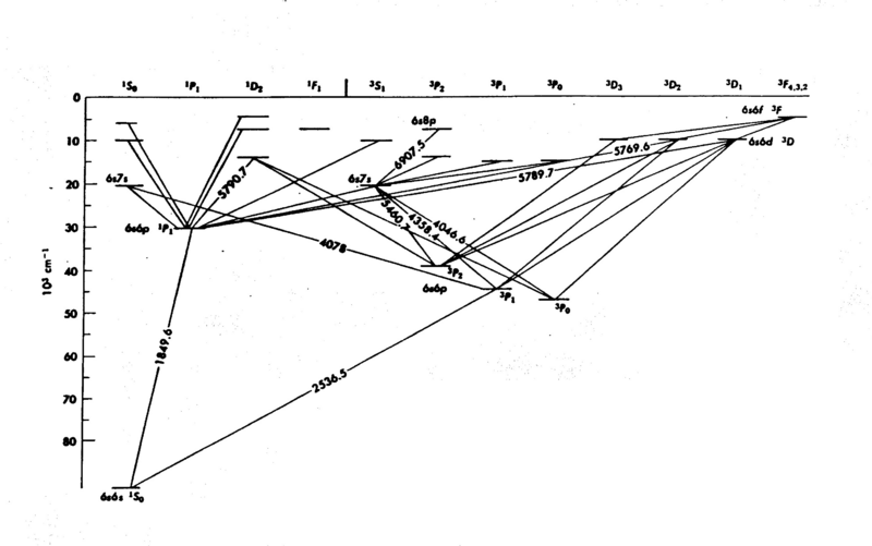
The energy levels of mercury (Hg) are shown in Fig. 1; it is easy to see that the internal structure is complicated - a consequence of the many electrons in the atom. The diagram gives considerable information you need to know for this experiment. The numbers associated with the lines drawn between the energy levels are wavelengths (in Angstroms Å). In the present experiment we explore only the energy levels 63P on the diagram, the first group of excited states. The electrons do not acquire enough energy to excite many of the other levels.
The Franck-Hertz apparatus consists of an evacuated glass envelope containing a cathode, screen, plate and a small drop of mercury, which can be vaporized by heating. The plate is always kept slightly negative with respect to the grid (that acts as an anode, i.e. accelerates the electrons) and both are set at various positive voltages with respect to the cathode. As the grid potential is raised, the plate current increases accordingly. For accelerating voltages below 5V all collisions with mercury atoms will be elastic (kinetic energy below about 5 eV). Hence, these electrons are energetic enough to overcome the negative plate-grid potential and are collected by the plate. The current flowing in the tube depends upon both the number of charged carriers (electrons) and their velocities (j = nev). Thus a significant change in the particle velocity can affect the size of the current. Once electrons with more than about 5eV energy excite a mercury atom, they slow down and the current flowing in the tube drops. If there is a larger voltage across the tube so that the electron can be re-accelerated to ~ 5 eV after giving it up once in the first collision, then we can see decreases in the current at higher voltages corresponding to a repeated inelastic collision. This process can yield a cyclic rise and fall of the current with the voltage.
|
Figure 1 - Energy Levels of Mercury.
|
Procedure
Required Components
- Franck-Hertz Unit
- Ramp Generator
- DC amplifier
- Power Supply for DC amplifier
- Oscilloscope
- Current Amplifier
- Filament AC voltage power supply
- Variable Resistor
- DC bias power supply
- Variac
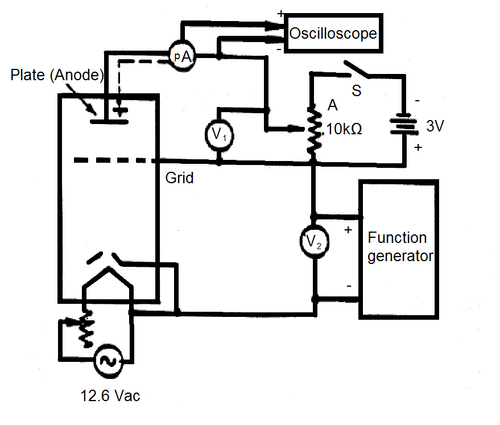
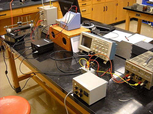
The experimental circuit is shown in Fig. 2a) and 2b). This will be set up prior to the experiment but should be checked, make sure you understand the purpose of each component before proceeding.
|
Figure 2a - Experimental Schematic.
|
|
Figure 2b - Experimental Setup.
|
Setting up the Ramp Generator and Oscilloscope
For this experiment, we require voltage sweep from 0 to 35 V which is isolated from ground. Most function generators you find around the lab cannot give such large amplitudes, so we will need to use a power supply that will be controlled by a ramp generator. Two power supplies (GW Instek GPS-1850D) connected in series will be controlled by a function generator (model:ASFG-2R) to generate the voltage sweep from 0 to 35 V. Note that neither output of the power supply is referenced to ground. In order to view the amplifier waveform, we will use an oscilloscope. Many oscilloscopes are designed in such a way that the outer conductor of its input jacks are automatically connected to ground. This will not work for our situation, since we need the sweep voltage to be unreferenced to ground. Therefore, we will need to operate the scope in a more advanced manner to observe the sweep. We will take the negative output of the power supply and connect it to the inner pin of CH2, and the positive output of the power supply will be attached to the inner pin of CH1 on the scope. Using the MATH function on the scope, we can display CH1-CH2, which is our sweep voltage of interest, without having connected anything to the outer conductor of the oscilloscope and forcing a ground in the circuit where one is not desired. Note, if you cannot attain a 0 - 35V ramp voltage without distortion, lower the ramp frequency.
- Turn on the sweep generator and select a triangle waveform.
- While observing the CH1-CH2 MATH signal as described above, adjust the amplitude and offset to get a 0 to 40 V triangle wave.
- Set the frequency to be a few tens of Hz. (You may want to try changing this value later).
Turing on the Heater and Electron Filament.
Since the vapour pressure of Hg is low at room temperature (p ≈10-3 mm. of Hg) the temperature must be raised to ~160ºC to reduce the mean free path of electrons in the Hg gas. This is accomplished using the Variac. Setting the dial to 60 should be high enough to raise the temperature of the experiment high enough. Be careful not to touch the experiment since the outside wall of the unit will also get very hot. The heating might take some time; make sure the temperature stabilized at the desired value before proceeding. Watch the thermometer to check the stability of the temperature. Once you turn on the heater, switch on the filament voltage using the switch on the power cable. This voltage level, and hence the magnitude of the electron current, can be controlled using the variable resistor.
Observing the Signal
Electrons liberated from the filament and accelerated to the detector plate which do not collide with an Hg atom will register as a current. This current is amplified by the current amplifier and can be viewed on the a free channel of the oscilloscope. It is a good idea to have the range setting of the current amplifier to be the lowest possible without saturating the signal. Note that evidence of collisions with Hg atoms will result in a deficit of current at specific accelerating voltages. This will be observed as dips on the oscilloscope trace. It is the origin and properties of these dips which is the focus of this experiment.
When the temperature is stable you can record the current-voltage characteristic of the Franck-Hertz tube. The current-voltage trace can be recorded from the connected oscilloscope after closing the (S) connection. Make sure the signal you observe does not have horizontal clipping (the peaks cut off), this can be fixed by changing the settings of the Pico-Ammeter or the potentiometer next to the 12.6 Vac transformer. (What is the meaning of the vertical cut-off?)
Record an I-V curve for a lower oven temperature (between 130ºC and 145ºC). Repeat for other temperatures, so that you may comment on the effect of the Hg pressure in the tube.
Saving the Scope Traces
Using the computer to the computer to the right of apparatus.
- Run National Instruments LabView 8.2.1.
- Open the recent file "FrankHetrz read scope.vi".
- Execute the program by clicking the arrow icon near the top left of the window.
- Enter a file name without extension when prompted and select if you want a comma separated file (.csv is automatically added). The default is tab separated (.txt).
- The data is saved in the "FrankHertz Data" directory on the desktop.
- You can now email yourselves the data file using your email client's web interface.
Measurements
Find as many values as you can of the excitation energy ("excitation potential") from your record. Repeat these measurements for 10 different temperature values. Perform a full error analysis and compare your results with the expected values.
Questions
- What effect do you find the temperature has on the I-V trace? Show this graphically.
- Explain the effect of changing the grid-to-plate voltage (V1)?
- Find out what is meant by "contact potential" in the Franck-Hertz tube and explain how it could be determined. Can you estimate it from your record?
- Determine from simple classical mechanics (using a head-on collision with recoil at 180 degrees) what fraction of an electron's kinetic energy can be transferred to a mercury atom in an elastic collision. Derive an approximate value of the fraction.
- Why are the other levels not observed? (e.g. 63P2, 63Po, 61P1.)
References
- Brehm, J., Mullin W, Modern Physics, p. 168
- Halliday, D., Resnick, R., Physics I, pp. 522-24.
- Carpenter, K.H., Amer. J. Phys. 43 (1975) 190.
- Hanne, G.F., “What really happens in the Franck-Hertz experiment with mercury?” Am. J. Phys. 56 (1988) 696.
- Huebener, J.S., Amer. J. Phys. 44 (1976) 302.
- Liu, F.H., “Franck-Hertz expt. with higher excitation level” Am. J. Phys. 55 (1987) 366.
- Preston, D., Dietz, E., The Art of Experimental Physics, pp. 197ff.


