Main Page/PHYS 3220/Speed of Light
Contents
A Measurement of the Velocity of Light: The Foucault-Michelson Experiment
Introduction
Light can be described as a periodic electromagnetic plane wave which carries energy in the form of an electromagnetic field. The electric and magnetic components can be written as:
This represents a monochromatic (single-frequency) beam travelling in the + z direction having a wavelength λ and frequency v (related by λ ν = c). The angle
is called the phase of the plane wave. A point on the wave having a constant phase (e.g. the peak of a sine wave) moves at a velocity determined by setting the time derivative of the constant phase equal to zero
The latter quantity vλ is called the phase velocity of the plane wave. From the above we find that in vacuum the phase velocity of monochromatic light is frequency (colour) independent. This quantity is known to high precision and is called the velocity of light c. We will determine the value of c in this experiment.
In this experiment, the light source is a laser, which provides a monochromatic beam. However, the laser beam is reflected from a spinning mirror, producing pulses of light with a band of frequencies centred on the fundamental optical frequency. (Why do the light pulses give rise to a band of frequencies?) While an accurate analysis would require the concept of group velocity, the length of the pulses are such that we may treat the light as monochromatic in our experiment, and thus do not need to distinguish between group and phase velocities.
Method
Many methods for the determination of the speed of light have been developed. Since c = Δs / Δt is large, i.e. ~3 x 10⁸ m/sec., its measurement in the laboratory necessitates the measurements of small time increments Δt, for modest values of Δs. One may employ large path lengths of celestial dimensions to increase Δt to a value which may be recorded more accurately. This latter method was used in 1675 by Roemer (Δs = 1.86 x 10⁸ miles (the diameter of the Earth's orbit) gives Δt = 1000 sec). One can also perform the timing of the passage of light from its source to a distant mirror and then back to the source.
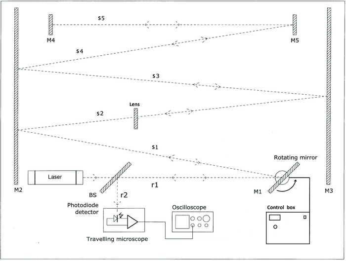
The rotating mirror method of Foucault, and later Michelson, provides a compromise between these two approaches. In this experiment, shown in Fig. 1, a beam of light from a laser is reflected from a rotating mirror (M1) along a measured path by way of a series of secondary mirrors (M2, M3, M4, M5), which reflect it back along the original path to the rotating mirror. While the light pulse has been travelling along this path, the mirror has rotated slightly so that the returning light pulse reflected from the new position of the mirror will deviate a small distance Δx from its original path. Relating the resulting deflection of the returning beam to the time taken for the mirror to rotate, and thus to the known path length, c is determined.
Referring to Fig. 1, the distance travelled by the light pulse is
| (1) |
The measured displacement of the returning pulse from its original position is
| (2) |
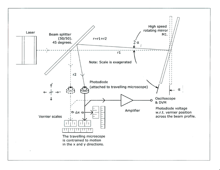
where α is the mirror’s rotation angle expressed in radians. Fig. 2
The time required for the mirror to rotate through this angle is
where ω = 2πf is the angular frequency of rotation of the mirror . Thus
| (3) |
hence combining equations 1 and 2, we have
| (4) |
|
Figure 1 - Experiment setup.
|
Procedure
CAUTION: Laser light is dangerous. Do not look directly into the beam. Understand the beam path of the laser source before switching the laser on.
Set up the apparatus as shown in Fig. 1. (Check if it has already been aligned for you!). The beam from the laser travels a long path to the fixed mirror and back again, reflecting in both directions from the rotating mirror. It finally reflects from BS, a beam splitter, onto the scale. Notice that the lens positioned perpendicular to the S2 beam path introduces a negligible variation in Δs but adjusts the resulting beam-size to a more useable magnitude. The rotation frequency of the mirror is controlled by a control box with a digital display of the rotation frequency. (Do not run the motor at maximum frequency for long time periods!)
The laser beam must be optically aligned at a slight upward angle with respect to all the other components. Once a component is aligned, do not disturb it, even slightly, or the entire process may have to be repeated! This can amount to a few hours of your time.
Turn the mirror motor off. Aim the laser so that it strikes the rotating mirror (M1). By gently turning the wheel under the motor, turn mirror M1 until the beam is reflected back just above the beam origin. Adjust either the actual position or the levelling screws as necessary. Then turn mirror M1 until the beam reflects off of mirror M2. Adjust mirror M2 until the beam is reflected back onto mirror M1 and the beam origin. (Avoid adjusting the vertical position of the apparatus, aside from M4 and M5, unless absolutely necessary!) Repeat these steps until the beam strikes mirror M5 and reflects back the whole way to mirror M1 and the beam origin. You will need to adjust both mirrors M4 and M5 until the beam retraces its path, that is, with no secondary images. Finally, align the beam splitter (BS), with equal distances to the laser and graph scale, placing the beam in a convenient location for your measurements. Can you think of a procedure to optimise this step? Hint: think in terms of any secondary images.
Do not in any way disturb the tables or you will have to begin again.
Part A
An initial, rough method for approximating the speed of light is outlined below. A mounted graph-paper is used to measure x.
**Make sure no one and nothing is touching the motor of the rotating-mirror before the power is turned on**
With the motor off, mark the location of the beam on the graph paper.
To give a good angular displacement of the light beam, the mirror should be rotating at about 400 cps (= 24,000 rpm). Accelerate the motor by slowly turning the dial on the control box.Do not use the “max Rev/sec” button. At this recorded frequency of rotation of mirror M1, mark the new beam location on the graph paper. Notice that it is not the bright line you have to mark, but the dim spot underneath it. (What is the reason for the bright line?)
From the measured displacement x and frequency f calculate the speed of light. Include a discussion of the uncertainties involved in this set-up. How could this set-up be improved yield more accurate results?
Part B
The method and measuring equipment are now modified to allow an improved estimate of c.
- Replace the graph paper with a photodiode detector, mounted on a leveled travelling microscope, as shown in Fig 2. The oscilloscope measures both the pulse amplitude and rotation frequency directly. The travelling microscope allows both horizontal and vertical measurements of image movement.
- At a number of frequencies, record the pulse-amplitude distributions, both horizontal and vertical. From this, determine the position of the pulse maxima. Graph these x values as a function of frequency. Include an error analysis in your report. Your least-squares analysis should give a value and precision estimate of x. Is the least-squares fit a satisfactory method? Measure exactly the position of the optical components. Substitute these values to determine c. Why do you see a spot image? (Why is it not a line image?)
|
Figure 2 - Use of a photodetector to determine pulse amplitude and period directly.
|
You have to keep in mind the following when performing the measurements and analysing your data. The displacement that you record for the photo-detector at maximum amplitude has a significant uncertainty (since the photodiode is larger than the observed laser beam, the maximum is flat). Devise a way to reduce the uncertainty in your measurements. (How do you think this uncertainty can be minimised further?) Investigate how your error estimate improves as the number of data points taken increases. Derive an error estimate for your speed of light measurement, and comment about whether the agreement with the accepted value improves as you increase the number of data points (for different rotation frequencies).Do you expect to see the same effect if you use different s values? Verify this by changing s5 (move mirror M4 closer to mirror M5).
Should you use the origin (i.e., location of the spot when the mirror is stationary) to obtain an absolute scale for the displacements or not? If yes, then you could constrain the fit to go through the origin.


