Main Page/PHYS 4210/Zeeman Effect
Contents
Zeeman Effect
In this classic experiment that predates the development of quantum mechanics one investigates the light emitted by atoms in the presence of a homogeneous magnetic field. Of particular interest is the observation that this light is polarized in the presence of a magnetic field. The high-resolution spectroscopy required to resolve the line splittings is performed with a multiple-beam interferometer called a Lummer-Gehrcke plate which is similar to a Fabry-Perot interferometer.
Key Concepts
|
|
Required Components
- Magnet Power Supply
- Electromagnet
- Discharge Power Supply
- CCD Camera
- Lummer-Gehrcke Plate
- Polarizers and Waveplate
Introduction
The Zeeman effect is a powerful demonstration of the splittings of magnetic sublevels in an angular momentum multiplet. Many aspects of the emission of light by excited atoms, particularly when exposed to strong magnetic fields (B) were understood by Lorentz in a classical model [1][2] before the advent of quantum mechanics. It is possible to understand the changes to classical electron orbits due to the Lorentz force in a 3D harmonic oscillator model. When one complements this with the idea that electromagnetic waves are transverse (the associated electric and magnetic fields of the EM wave oscillate in a plane perpendicular to the propagation direction of the wave), one can understand why circularly polarized light emerges as the atoms are observed in a direction longitudinal with the external B field, and why they appear as plane-polarized as viewed from the transverse direction. The understanding in the classical framework helps to build an intuition about the problem.
In the modern quantum mechanical description [2][3][4] one has to take into account that the presence of the B field singles out an axis. The additional interaction term between the magnetic moment of the electronic state (proportional to the z component of the total angular momentum) and B serves to split the magnetic sublevels of states with non-zero angular momentum. The additional interaction forces the use of this axis as a quantization axis. Without an external field one usually picks a z axis, but should arrive at results that are independent of this choice. To obtain the observed result that the light emanating from spontaneous transitions without an external field is unpolarized, one has to average over random orientations of the quantization axis. The observation that a definite orientation is singled out as quantization axis in the Zeeman effect is sometimes referred to as ‘space quantization’.
The problem can be illustrated by using pure orbital angular momentum states, i.e.,ignoring spin, and considering an np - ms transition. This transition is an allowed electric dipole transition, since a single unit of orbital angular momentum is changed, and this difference of one unit is carried away in the form of the spin for the spontaneously radiated photon. The important quantity to watch is the change in the projection of the orbital angular momentum, which can be +1, 0, -1 depending on the choice of the magnetic sublevel.
A transition 2p0 - 1s is associated with the emission of linearly polarized light with the oscillating electric field vector aligned with the z axis, with the wave propagation vector being orthogonal to this axis. This can be understood from the fact that the only non-vanishing matrix element for the dipole operator is <1s|z|2p0>. Similar calculations show that the transitions originating in the m = 1 and m = -1 sublevels result in circularly polarized light being emitted, which can propagate in the z direction only. One of the fascinating aspects of the Zeeman experiment is the following. For field-free atoms no axis is singled out, and thus, one has to include all possible orientations of the z axis, which results in the prediction that the light emitted from free atoms is unpolarized. However, once a homogeneous magnetic field is applied, an axis is singled out in space, which becomes the natural quantization axis. By probing the polarization of the spontaneously emitted light of atoms in the presence of a magnetic field one can verify that indeed the turn-on of the field causes a repopulation of the magnetic sublevels in a way that corresponds to the classical predictions of the Lorentz model. Thus, it is necessary to observe the light emitted longitudinally and transverse to the magnetic field.
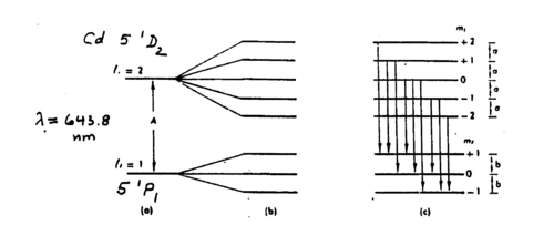
The general theory of the Zeeman effect is complicated by the fact that the total angular momentum, i.e., added orbital and spin angular momentum of the active electron has to be considered. Based on orbital angular momentum alone the magnetic moment of an electron in a non-zero m sublevel is an integer multiple of the projection lz. Once one couples l and s to form j = l + s, the magnetic moment can be, but need not to be an integer multiple of jz, and the proportionality is given by the Lande factor g. The Lande factor can take on half-integer numbers for the initial and/or final states involved in the transition. One distinguishes between the normal and anomalous Zeeman effects depending on whether this complication arises or not [5]. The anomalous effect is rather common in atomic transitions, but in this experiment a transition with the normal Zeeman effect has been selected. The red line in cadmium (643.8 nm), which is the equivalent of the yellow line in mercury, cf.. the Grotrian diagram shown in the appendix, and the level diagram in Fig. 1 (which is Fig. 7.3 from [5]).
|
Figure 1 - Level diagram for the Cd 643.8 nm transition with and without B field.
|
From an experimental point of view a high demand is placed on the optical resolution of the interferometer. The idea is to inspect the interference pattern for a given line and to observe the quantitative changes in the pattern as the B field is applied to determine the wavelengths of the various components. The high resolution required can be obtained from multiple-beam interferometers, such as the Fabry-Perot (FP) interferometer [1,3]. Melissinos [3] discusses the analysis of the circular fringe pattern as produced by the FP. An easier alternative is provided by a special instrument that perfects the same method, called a Lummer-Gehrcke (LG) plate [1]. Since its interference pattern is more complicated to derive, you should concentrate on understanding the principles of multiple-beam interferometry using the FP and be aware of the analogies. Note that the FP has a wide range of applications in optics.
|
Figure 2a - Multiple reflection between the surfaces of a Lummer-Gehrcke plate.
|
|
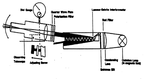
Figure 2b - Apparatus for the Zeeman experiment with a Lummer-Gehrcke plate.
|
|
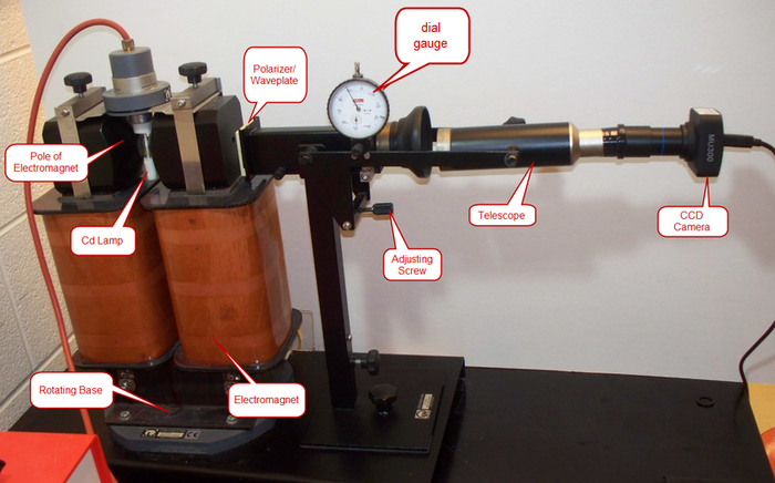
Figure 2c - Apparatus for the Zeeman experiment.
|
The LG plate shown as part of the apparatus in Fig. 2 consists of a precisely polished quartz glass plate of given thickness d with a prism attached at one end so that light entering from the slit has an angle of incidence on the plate that is near the critical angle. This results in some refractive transmission and mostly reflection at the glass/air surface. The reflected light inside the glass plate undergoes multiple ‘bounces’ of this type (interior reflection and partial refractive transmission). Two different interference patterns emerge when looking at a grazing angle at the top or bottom of the LG plate. The pattern formed at the top shows sharp bright lines on a dark background. In contrast to a Michelson interferometer a multiple-beam interferometer such as the FP and LG can produce an uneven interference pattern [1,3].
The separation between the fringes that appear without the magnetic field depends on the angle of observation. This spacing ΔA has to be determined for the particular fringe chosen for observation. As a magnetic field is applied each bright fringe splits either into two or into three depending on the orientation with respect to the magnetic field. To obtain a quantitative measure of the Zeeman effect, one needs to determine the B dependent splitting ΔS relative to ΔA. Making use of the ratio eliminates the need to know the optical magnification, observation angle and distance from the plate. The frequency splitting depends also on the LG plate thickness d (as in the FP case), and additionally on the index of refraction η of the quartz glass. In the FP case this would be equal to 1, but there are versions of the experiment where the evacuation of a sealed FP interferometer is used to produce a scanning effect in the fringe pattern [4]. The frequency splitting can be written as
| (1) |
The corresponding energy difference should equal
| (2) |
One common method of determining the electron charge-to-mass ratio is through eq (2). Our interest is, however, to determine the energy splitting as a function of the magnetic field strength B.
In our version of the Zeeman experiment the intense red Cd line at 643.8 nm is used. For optical transitions Cd acts as an effective two-electron system, i.e., it has a He-like configuration, as has Hg. Compare the Grotrian diagram shown in Fig. 1 to the one for mercury provided in the appendix (cf.. the Franck-Hertz experiment). In order to understand the selection rules for allowed electric dipole transitions follow the arguments given in ref. 4 in the context of the HeNe laser experiment. The two active electrons have combined orbital angular momentum L = l1+l2, spin S = s1+s2, and total angular momentum J = j1+j2. Allowed transitions require a change of one unit in L and J to make up for the spin of the photon, considering that spin flip is unlikely. Using (2S+1)LJ notation (with L = 0 denoted as S, L = 1 as P, L = 2 as D, etc) we have for the relevant line a 1D2 - 1P1 transition. This means that the spins are paired up (spin singlet) and that in nonrelativistic notation a 5s5d to 5s5p transition takes place. In Hg the equivalent line at the n = 6 level is the yellow line at 579 nm. The shift of the same line towards yellow is the result of having an additional electron shell in the core. What wavelength is associated with this transition in He?
For the advanced student: note that the initial level splits into 5 sublevels MJ = -2,-1,0,1,2 , while the final state has MJ = -1,0,1. They split equidistantly and one can group the nine possible transitions according to the allowed ΔM = -1,0,1 (cf.. Ref. 3 Fig. 7.3). To understand the polarization of the emitted light in the presence of the external B field note that for an electromagnetic wave its electric, magnetic fields and the wave propagation vector k form a right-handed coordinate system. Understand the validity of the dipole approximation (the wavelength λ is much longer than atomic dimensions) and how the electric field of the EM wave can be replaced by a constant vector times a temporary oscillatory factor (ref. [3,6]). Convince yourself why no linearly polarized light can be observed in the longitudinal direction as the magnetic field is turned on. Correspondingly understand why circularly polarized light as observed in the longitudinal direction must appear as linearly polarized when observed in a direction transverse to the B field. Why can all three components associated with the ΔM = -1,0,1 selection rule be observed in the transverse direction?
To verify these predictions about the polarization states of the light when the B field is turned on you need to recall some optical properties of polarizers and of quarter-wave plates (cf.. Ref.1). By placing these in the correct order you can verify the following:
In the transverse direction, use a linear polarizer to identify the polarization states of the three components with B turned on; what happens for B = 0?
NOTE: To perform these tests, place the polarizers (and/or waveplates) before the the LG plate, not in between the LG plate and CCD.
In the longitudinal direction, use a quarter-wave plate convert the circularly polarized (CP) light to two perpendicular linearly polarized components corresponding to left- and right CP light respectively. Use a polarizer to extinguish each of these components separately; what happens for B = 0?
Collect sufficient data for both observation directions to demonstrate the linearity of the line splitting with the magnetic field. You will need to perform a calibration of the magnetic field as a function of the current and should comment on possible saturation effects, i.e., a linear behaviour of the splitting with B, but non-linear with the magnet current I at strong fields, where part of the electric energy may be converted to heat. Determine the gyromagnetic ratio (g) from your observations.
Warning: The Cd lamp emits ultraviolet light in addition to other lines such as the red Cd line. The apparatus contains a narrow-band red filter so that your eyes are protected when observing through the telescope. Avoid looking into the lamp itself (even though it is rated to be safe), i.e., cover the apparatus with a sheet of paper to reduce unnecessary eye contact with the lamp. The lamp takes several minutes to reach a proper operating temperature for the red line to be visible.
Obtain assistance when changing the observation direction from transverse to longitudinal or vice versa!
Using the CCD Camera
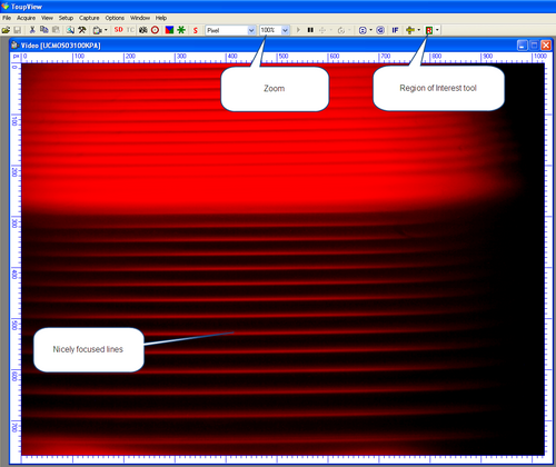
A CCD camera (AmScope MU300) is provided to allow for easy viewing of the lines. To operate the CCD, run the program "ToupView", then select Acquire-> Live Capture-> UCMOS03100KPA from the menu. A window will appear which is the live image being collected by the CCD. The brightness of the image can be changed using the Setup -> View Souce Properties -> Expose tab. A reasonable choice of values is an Exposure of 700ms with an Analog Gain of 3. Correct adjustment of the support system will allow you to clearly view the lines. Sliding of the CCD camera in and out will allow for focus. You can Save the image using Capture -> Capture a Frame command.
|
Figure 3- ToupView CCD Camera Interface.
|
Once you are able to see nice clear lines as shown in Figure 3, use the Region of Interest tool to focus in on a few lines in center. You can now use the Zoom to expand the image. One the left margin of the video image, there is a scale showing the pixel number. You can use this as a fixed reference point- as you increase the applied magnetic field, the line will split into sublevels, check the dial gauge, and then use the adjusting screw to place the shifted line back to the pixel number of the original line, then check the new reading of the dial gauge and record the measurement.
References
- ↑ Jenkins F.A., White H.E., Fundamentals of Optics, McGraw-Hill
- ↑ 2.0 2.1 Brehm J.J., Mullin W.J., Introduction to the Structure of Matter, Wiley
- ↑ Merzbacher E., Quantum Mechanics, Wiley
- ↑ Bethe H.A., Salpeter E.E., Quantum Mechanics of One- and Two-Electron Systems, Springer
- ↑ 5.0 5.1 Melissinos A.C., Experiments in Modern Physics, Academic Press
- Jenkins F.A., White H.E., Fundamentals of Optics, McGraw-Hill
- Brehm J.J., Mullin W.J., Introduction to the Structure of Matter, Wiley
- Melissinos A.C., Experiments in Modern Physics, Academic Press
- Preston D.W. Dietz E.R., The Art of Experimental Physics,Wiley
- Merzbacher E., Quantum Mechanics, Wiley
- Bethe H.A., Salpeter E.E., Quantum Mechanics of One- and Two-Electron Systems, Springer
- Radzig A.A., Smirnov B.M., Reference Data on Atoms Molecules and Ions, Springer 1985.
Appendix
- Data for the Lummer-Gehrcke plate [from Leybold’s manual]: d = 4.04 mm η = 1.4567
- Grotrian diagrams for Cd, Hg, and He taken from ref. 7. A copy of these are in the binder in the laboratory.


