Main Page/PHYS 3220/Viscosity
Viscosity
The purpose of this experiment is to determine the viscosity of a liquid and to find the variation of viscosity with temperature.
Theory
When a solid is subject to a shearing stress it deforms until the internal elastic forces of the solid exactly balance the external forces. Thus a finite force applied to a solid produces a finite deformation. If a similar force is applied to a liquid, however, the deformation increases indefinitely (the liquid flows). The flow can be imagined as the movement of adjacent layers over one another. The Newtonian friction caused by the relative motion between adjacent layers retards the flow and is called viscosity. This frictional force was assumed by Newton to be proportional to the velocity gradient perpendicular to the direction of the motion of the fluid, i.e., to dv/dr.
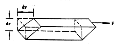
Consider an element of volume in a fluid as shown in the following diagram (ref. 1)
|
Figure 1 - Element of volume of a liquid in a tube.
|
The shearing stress on this element of volume is F/A where F is the force on the upper surface and A is the cross section. The shear is given by the ratio between the lateral displacement between the two surfaces to the separation between the surfaces. Thus, if we assume that the upper surface is moving with a velocity, dv, greater than that of the lower surface, the amount of shear occurring in unit time is dv/dr. The coefficient of viscosity or simply viscosity is defined as follows (for streamline motion).
| (1) |
The c.g.s. unit of viscosity is called the poise; it represents the viscosity of a substance that acquires a unit velocity gradient under the influence of a shearing stress of 1 dyne/cm2.
One method of measuring viscosity is to determine the flow of a liquid through a capillary tube. Let us consider how to measure viscosity in this way.
When a liquid flows through a narrow tube so that each particle moves parallel to the axis of the tube with constant velocity, the motion is said to be regular or streamlined. In this case, liquid in contact with the walls is at rest while the velocity is a maximum at the centre of the tube.
|
Figure 2 - Streamlined flow of a liquid in a tube.
|
We imagine the liquid as being divided up into a number of thin cylindrical shells, each shell sliding on the other. The viscous drag, f, per square cm. of one layer on the other is given by
| (2) |
For a cylinder of radius, a, length l, through which a liquid is flowing under a pressure differential, p, the total viscous drag balances the force due to the pressure difference.
| (3) |
Assuming that there is no radial flow the pressure is constant over any given cross-section. At r = a, v = 0, while at r = r, v = u, thus
| (4) |
The quantity of liquid, Q, flowing through the tube per second is given by Poiseuille's formula,
| (5) |
Thus, by measuring the quantity of liquid transferred through a capillary tube per unit time subject to a specific pressure difference, the viscosity of the liquid may be determined.
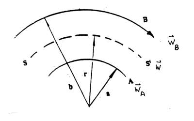
The viscosity may also be determined using the concentric cylinder viscosimeter. Consider a liquid between two concentric cylinders as illustrated in Figure 3.
|
Figure 3 - Liquid between concentric cylinders.
|
The outer cylinder is moving with angular velocity wB. If the liquid adheres to the walls of the cylinder, a shearing takes place in which concentric cylindrical layers of the liquid slip over each other with the angular velocity w increasing progressively from zero at the stationary cylinder to wB at the rotating one. Now, the rate of shear is given as
The quantity of liquid, Q, flowing through the tube per second is given by Poiseuille's formula,
| (6) |
Only the second term produces a viscosity effect, since a velocity gradient is needed to have relative slipping of layers and the associated friction. Thus,
| (7) |
If a torque L is applied to the rotating cylinder, (see Figure 3), the tangential force at the boundary SS' equals L/r and integration over r from A to B yields
| (8) |
Note that this formula is also valid if the inner cylinder is rotated with angular velocity wB while the outer cylinder is held stationary.
For cylinders closed at either end, equation (8) is modified to take into account the friction between the two ends of the cylinders according to
| (9) |


